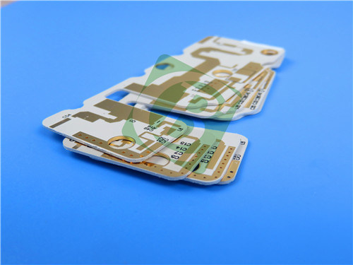
| MOQ: | 1 stks |
| Prijs: | USD9.99-99.99 |
| Standaardverpakking: | Vacuümzakken+dozen |
| Leveringstermijn: | 8-9 werkdagen |
| Betalingswijze: | T/t |
| Toeleveringskapaciteit: | 5000 pcs per maand |
This 2-layer rigid printed circuit board (PCB) is tailored for high-performance commercial microwave and RF applications, capitalizing on the outstanding properties of Rogers RO3003 ceramic-filled PTFE composite laminates. It provides stable electrical performance across a broad spectrum of temperatures and frequencies, rendering it a dependable option for crucial systems such as automotive radar, 5G mmWave infrastructure, and advanced driver assistance systems (ADAS).
1. PCB Specifications
The PCB’s construction is optimized for precision, reliability, and compatibility with high-frequency design requirements, with key details outlined in the table below:
| Parameter | Specification |
| Base Material | Rogers RO3003 (ceramic-filled PTFE composite laminate) |
| Layer Count | 2 layers (top and bottom outer copper layers) |
| Board Dimensions | 33mm × 63mm per unit (1PCS) |
| Minimum Trace/Space | 5 mils (trace width) / 7 mils (trace spacing) |
| Minimum Hole Size | 0.3mm; no blind vias supported |
| Finished Board Thickness | 1.4mm |
| Finished Copper Weight (Outer Layers) | 1oz (equivalent to 1.4 mils or 35μm) |
| Via Plating Thickness | 20μm |
| Surface Finish | Immersion Gold (ensures excellent conductivity and corrosion resistance) |
| Top Silkscreen | Black (for clear component labeling and assembly guidance) |
| Bottom Silkscreen | No |
| Top Solder Mask | No |
| Bottom Solder Mask | No |
| Quality Assurance Testing | 100% electrical testing conducted prior to shipment (ensures no open/short circuits) |
2. PCB Stack-up Configuration
The 2-layer stack-up is designed to maximize the performance of the Rogers RO3003 substrate, ensuring stable signal propagation and structural integrity:
| Layer | Thickness |
| Top Copper Layer (Copper_layer_1) | 35μm |
| Rogers RO3003 Substrate | 50 mils (1.27mm) |
| Bottom Copper Layer (Copper_layer_2) | 35μm |
3. Standards & Global Accessibility
This PCB adheres to industry-leading standards and is readily available worldwide, ensuring consistency and convenience for global customers:
Artwork Format: Gerber RS-274-X (the industry-standard format for PCB manufacturing, compatible with all major design software and fabrication equipment)
Accepted Quality Standard: IPC-Class-2 (meets rigorous requirements for performance, reliability, and consistency in commercial and industrial applications, including thermal cycling and environmental durability)
Availability: Globally accessible (no regional restrictions, ensuring timely delivery for projects worldwide)
![]()
4. Rogers RO3003 Substrate: Key Details, Features & Benefits
The PCB’s exceptional performance is rooted in the superior properties of the Rogers RO3003 laminate—a ceramic-filled PTFE composite tailored for high-frequency applications.
4.1 Introduction to Rogers RO3003
Rogers RO3003 is a high-frequency laminate designed for commercial microwave and RF systems. It eliminates the typical "step change" in dielectric constant (Dk) near room temperature that plagues standard PTFE glass materials, ensuring consistent performance across operational conditions.
4.2 Critical Material Features
RO3003’s features are optimized for high-frequency reliability and stability:
Material Composition: Ceramic-filled PTFE composite (balances low loss and mechanical strength)
Dielectric Constant (Dk): 3 ± 0.04 at 10 GHz / 23°C (tight tolerance for predictable signal behavior)
Dissipation Factor: 0.001 at 10 GHz / 23°C (ultra-low signal loss, critical for high-frequency systems up to 77 GHz)
Decomposition Temperature (Td): >500°C (resistant to high temperatures, suitable for harsh operating environments)
Thermal Conductivity: 0.5 W/mK (efficient heat dissipation to protect sensitive components)
Moisture Absorption: 0.04% (minimal water uptake, preventing performance degradation in humid conditions)
Coefficient of Thermal Expansion (CTE): X-axis 17 ppm/°C, Y-axis 16 ppm/°C, Z-axis 25 ppm/°C (measured from -55°C to 288°C; low in-plane expansion matches copper, reducing thermal stress)
4.3 Core Benefits of Rogers RO3003
These features translate to tangible advantages for design and end-use:
Low Dielectric Loss for High Frequencies: Enables reliable operation in applications up to 77 GHz (e.g., automotive radar, 5G mmWave)
Excellent Mechanical Properties vs. Temperature: Maintains structural integrity across wide temperature ranges, supporting reliable stripline and multi-layer board constructions (even in harsh environments like automotive underhood systems)
Uniform Mechanical Properties: Works with a range of dielectric constants, making it ideal for multi-layer designs and hybrid assemblies with epoxy glass boards
Stable Dk vs. Temperature & Frequency: Ensures consistent performance for band pass filters, microstrip patch antennas, and voltage-controlled oscillators (VCOs)—critical for precision RF systems
Low In-Plane Expansion (Copper-Matched): Reduces stress on surface-mounted assemblies (SMAs), improving reliability in temperature-sensitive applications and ensuring excellent dimensional stability
Volume Manufacturing Compatibility: Economical pricing and scalable production processes, making it suitable for high-volume commercial projects
5. Some Typical Applications
- Automotive radar applications
- Global positioning satellite antennas
- Cellular telecommunications systems - power amplifiers and antennas
- Patch antenna for wireless communications
- Direct broadcast satellites
- Datalink on cable systems
- Remote meter readers
- Power backplanes
![]()